

Description
Technical Specification
Media
The trainer enables users to match the individual heat quantities to the corresponding type of transfer. The core element is a heated metal cylinder located at the center of the pressure vessel. The surface temperature of the heated metal cylinder is controlled.
Temperature sensors measure the surface temperature of the metal cylinder and the wall temperature of the pressure vessel. In addition to the heating power of the metal cylinder, it is possible to study the heat transport from the metal cylinder to the wall of the pressure vessel.
The pressure vessel can be put under vacuum or positive gauge pressure. In the vacuum, heat is transported primarily by radiation. If the vessel is filled with gas and is under positive gauge pressure, heat is also transferred by convection. It is possible to compare the heat transfer in different gases. In addition to air, nitrogen, helium, carbon dioxide or other gases are also suitable.
Heat transport by conduction is largely suppressed by adequately suspending the metal cylinder.
A rotary vane pump generates negative pressures down to approx. 0.02mbar. Positive gauge pressures up to approx. 1bar can be realized with compressed air. Two pressure sensors with suitable measuring ranges are available for the pressure measurement: a Perini sensor measures the negative pressure while a piezo-resistive sensor measures the positive pressure.
Experimental Capabilities
- Experiments in vacuum:
- Heat transfer by radiation.
- Determination of the radiation coefficient.
- Experiments at ambient pressure or positive gauge pressure.
- Heat transfer by convection and radiation.
- Determination of the heat quantity transferred by convection.
- Determination of the heat transfer coefficient based on measured values.
- Theoretical determination of the heat transfer coefficient based on the Nusselt number.
- Comparison of the heat transfer in different gases.
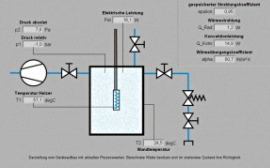
Circuit Diagram
The circuit diagram of the apparatus is given bellows such as: Heat transfer in the vessel:- Convection [Vessel filled with gas].
Software Diagram
The software diagram is given bellows such as: