
State-of-the-art Engineering Equipment
TH-305.01 | Single Cylinder Steam Engine


- 1 trainer.
- 1 set of hoses.
- 1 oil (100mL).
- 1 set of accessories.
- 1 set of instructional material.
- LxWxH: 1700x810x1440mm
- Weight: approx. 110kg
Description
Technical Specification
Media
In a steam engine, thermodynamic energy in the form of vapor pressure from steam generators is converted into mechanical energy. This can be used further downstream in the process to generate electricity or to power machinery and vehicles.
A steam power plant consists of a heat source for generating steam, a turbine or steam engine with a generator, and a cooling device for condensing the exhaust steam.
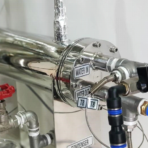
The trainer contains the main components of a steam power plant: a gas-fired steam boiler, a single-cylinder piston steam engine with a generator, a condenser, a feed water tank, and a feed water pump.
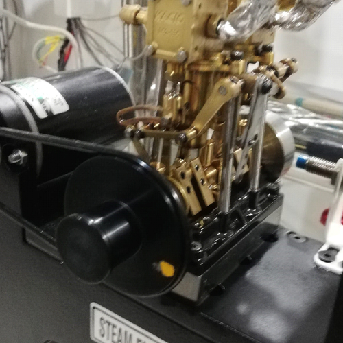
The steam boiler generates water steam and supplies it to the piston steam engine. A piston and a crank mechanism convert the energy from the steam into mechanical energy.
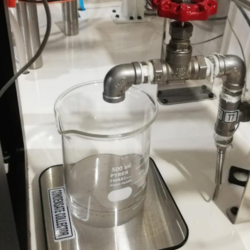
A generator in the form of a DC motor generates electricity from the mechanical power. Four light bulbs are used as consumers of the resulting electrical energy. The exhaust steam is condensed in a water-cooled condenser.
Safe operation is ensured by safety devices that monitor the boiler temperature and a safety valve.
Sensors record the temperature, pressure, and flow rate at all relevant points. The measured values can be read on displays. Current and voltage from the generator are measured and displayed in the experimental unit.
The circuit diagram of single cylinder steam engine is given bellows such as:
Experimental Capabilities
- Demonstration of the function of a steam engine.
- Familiarization with the components of a steam power plant and how they interact.
- Recording the vapor pressure curve.
- Effect of re-evaporation and back feed of cold water
- Determining fuel consumption, the amount of steam generated, the boiler efficiency, and the capacity of the condenser.
Circuit Diagram
- Feed water Tank.
- Feed Water pump.
- Steam Boiler.
- Steam Engine.
- Condensate Tank.
- T for temperature, P for pressure and F for flow rate.
Graphical Diagram
The graphical representation between pressure and volume is given bellows such as- Demonstration of a steam power plant with single-cylinder piston steam engine.
- Gas-fired boiler for steam generation.
- Water-cooled condenser.
- DC generator.
- Light bulbs as consumers
- Sensor and display for temperature, pressure, flow rate, voltage and current.
- Safety valve and temperature monitoring for safe operation.
- Steam engine
- Power: max. 5W.
- Speed: max. 1200min-1.
- Cylinder: Ø 20mm.
- Generator
- DC motor: max. 3,18W at 6000min-1.
- Gas-fired boiler
- Safety valve: 4bar.
- Gas connection 3/8“L (propane or butane).
- Measuring ranges:
- Temperature: 8x -20…200°C.
- Pressure: 0…6bar.
- Flow rate:
- 0…110L/h (gas).
- 15…105L/h (water).
- Voltage: 0…10VDC.
- Current: 0…250mA.
Any questions? We are happy to help...
+49 40 670 854 - 0
sales@gunt.de
Newsletter
About Us
EduTech Lahore excels in designing and supplying cutting-edge equipment for Engineering Education in Mechanical, Polymer Chemical, Civil and Control Engineering. Focused on meeting the demand for quality education, we offer cost-effective solutions for the latest teaching equipment.
Contact Info
Head Office (Asia)
EduTech
Lahore
Regional Partner Office (UK)
Sales Partner (Middle East) GCC International FZC
Leave a Message
WhatsApp us