
State-of-the-art Engineering Equipment
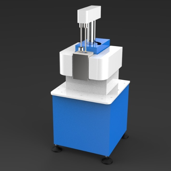
SM-111 | CAPPILARY RHEOMETER
- Intel Core i5 (7th Generation or above)
- Ram: 16GB
- Hard Drive: 500GB
- LCD: 21”
- Display resolution: 1280×1024
- Platform: Microsoft Windows (Windows 11)
- A single Ethernet port is required for connection to the rheometer.
Cappilary Rheometer
- D x W x H: 650 x 550 x 1100 mm (Approx.)
- Weight: 120kg Approx.
- D x W x H: 530 x 340 x 650 mm (Approx.)
- Weight: 30kg Approx.
Description
Technical Specification
Media
Mechanical Structure
Construction: The rigid frame design provides extreme mechanical strength and stiffness for a compact benchtop unit. A unique, safety interlock-protected, swivel design means that the actuated part of the rheometer can be moved to one side affording ease of access for cleaning and sample loading.- Motor over-current trip
- Emergency stop switch
- Fume extraction
- 89/392/EEC & 91/368/EEC - machinery safety accreditation
- More commonly, zero-length dies are used to directly measure the inlet pressure drop and measure the extensional viscosity using the Cogswell method.
- The twin-bore technique gives obvious experimental advantages including improved throughput since both experiments are preheated simultaneously. Alternatively, the software can be configured to run a two-material test which allows the measurement of the viscosity of two different materials simultaneously.
Working principle
Cappilary rheometer is a viscosity measurement device at a higher shear rate range compared to the rotational rheometer or the melt flow indexer.- Material is heated in the barrel to the test temperature.
- The piston pushes the material out of the barrel with a preset speed. (shear rate) And we measure the pressure of the molten material in the barrel with the pressure transducer.
- The pressure increases and gets to equilibrium. The pressure value at the equilibrium of the piston at that speed.
- Then the speed changes to the next preset value and measure the pressure value at that speed.
- By piston’s area and speed, you get a flow rate Q.
- You measure the pressure.
- Shear viscosity is shear stress divided by shear rate.
Software
The software is used to configure experiments and analyse the resulting data. It may also be used in stand-alone mode for analysis. The software is designed for high productivity and includes many ease-of-use features and very powerful analysis and reporting. The user interface is highly configurable to let you work in the way you want, and a series of user levels can be defined to restrict access to certain features of the software so that less advanced users can use the software without the risk of producing invalid results.Basic analysis
- Calculation of shear and extensional viscosity
- Calculation of power law index (n)
- Bagley and Rabinowitsch correction
- Non-Newtonian index
- Carreau, Cross, power law and polynomial curve fits
Derived curves
- Shear rate, melt volume, volumetric flow rate
- Facility to use data from the standard channels (force, pressure, temperature), or user-provided measurement channels to derive further curves
- A powerful set of functions is provided to allow user-defined calculations to be made on the captured data
Test types
- Shear rate sequence – twin bore
- Shear rate sequence – single bore
- Thermal degradation tests
- Pressure vs volume test
Rheometer control
- Manual crosshead control
- Temperature zone control
- Pre-condition sample (thermal stabilization and compression)
- Run pre-defined test
- Purge barrel contents
Die Database
- Database of available dies
- Support for capillary, orifice, and rectangular slot dies
Test information
- Test progress bar
- Real-time graphs of pressures, speed, and position
- Real-time calculation and graphing of rheological properties
Pressure equilibrium
- Automatic and manual
Units
- The software allows you to work in whatever units you choose – it provides by default SI, cgs and US units
- All numeric quantities (measured data and documentation information) are recorded along with their units, and when results are calculated their resulting units are calculated too, ensuring consistency and greatly reducing the potential for errors.
Documentation
- Two types of documentation information are saved along with the test data:
- automatically recorded documentation (transducer and die information for example), and user-entered documentation.
- Documentation fields are configurable depending on your particular requirements, and fields can be made mandatory to ensure that critical information is recorded for every test.
Graphs
- Graphs are used for displaying measured and calculated data. Multiple tests and multiple quantities may be displayed on the same graph.
- Highly configurable appearance including colours, automatic or manual axis scaling, linear or logarithmic scaling, and user-defined or labelling.
Tables
- Tables are used to display calculated results or documentation information.
- The results from multiple tests may be displayed in the same table.
- Flexible formatting includes colours, fonts, column headings, units, and the format of numeric results.
Data export
- Data can be exported to Microsoft Excel in native file format. There is also the facility to export data in CSV (comma-separated values) format, compatible with almost all numeric analysis packages.
Test database
- Test data may be saved either in individual files or in a test database (Microsoft Access format). Multiple databases may be created, for different users or different applications. Test data stored in files may be copied into the database and vice versa. A powerful search tool can be used to interrogate the database and find tests that match particular criteria: for example, by the date of the test, the type of sample, a shear viscosity falling outside specified limits, or a test performed at a particular temperature.
Auto-save
- An auto-save facility ensures that data from a test is never lost, and also imposes a consistent naming scheme for data files. Data can be automatically saved to files or to the test database.
User levels
- The software provides password-protected user levels. The software functions available to each level may be defined, preventing access to sensitive operations that might affect the accuracy of the data.
Saving settings
- Entire software configurations, or partial configurations, may be saved and later restored. This facility is useful both as a backup mechanism and also to allow quick switching between different test types (for example, single bore and twin bore).
Constant Shear and Extensional Tests
Measurement of shear or extensional stress and shear or extensional viscosity as a function of shear rate. Extensional tests are carried out with an orifice die.Constant Shear and Extensional Tests
Measurement of shear or extensional stress and shear or extensional viscosity as a function of shear rate. Extensional tests are carried out with an orifice die.Melt Fracture/Flow Instability
Accelerated shear rate ramp with continuous monitoring of the pressure to detect flow instabilities, such as melt fracture which may occur during flow through a capillary die.Drive
- Force range: upto 20kN
- Number of Bores: Double bore
- Maximum speed:600 mm/min
- Speed uncertainty: <0.25%
- Speed control: Automatic through software
- Drive: Direct-drive motor with a high-resolution encoder
- Feedback: encoder of 10,000 pulse giving 0.02μm resolution
- Force measurement: Extrudate tension measured via force on pulley-wheel
- Force resolution: 0.01N
- Linearity: <1% full scale
- Dynamic range in speed: 40,000:1
Temperature Control
- Type: zone measurement and control
- Temperature Range: Ambient to 400 ºC
- Sensors: Platinum resistance thermometers to DIN 43760
- Accuracy: ±0.5°C
- Uniformity: ±1.5°C throughout both barrel bores
- Temperature Control: <±0.5 ºC
Dies
- Material: Tungsten carbide
- Precision ±5μm
Barrel
- Bore diameter: 15mm
- Barrel bore length: 250 mm
- Barrel material: Nitrided steel
Pressure
- Pressure transducer ranges: upto 200 bar
- Pressure transducer accuracy: <0.5%
Power
- single-phase
- Neutral and Protective Earth
Any questions? We are happy to help...
+49 40 670 854 - 0
sales@gunt.de
Newsletter
About Us
EduTech Lahore excels in designing and supplying cutting-edge equipment for Engineering Education in Mechanical, Polymer Chemical, Civil and Control Engineering. Focused on meeting the demand for quality education, we offer cost-effective solutions for the latest teaching equipment.
Contact Info
Head Office (Asia)
EduTech
Lahore
Regional Partner Office (UK)
Sales Partner (Middle East) GCC International FZC
Leave a Message
WhatsApp us