
State-of-the-art Engineering Equipment
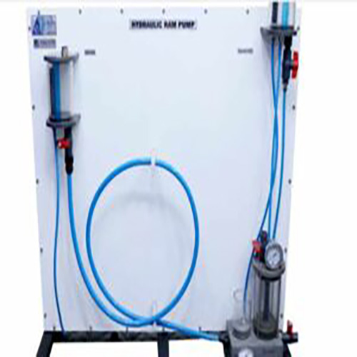
Hydraulic Ram Pump-Pumping by Water Hammer

- Functioning and operating behaviour of an axial turbine
- Closed water circuit contains axial turbine, pump and water tank
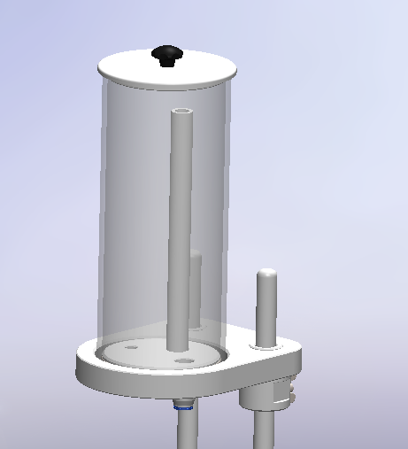
- Transparent housing for observing the stator and the rotor
- Turbine load using the wear-free and adjustable eddy current brake
- Valve for adjusting the volumetric flow rate
- Force sensor to determine the torque on turbine shaft
- Measurement of turbine speed with optical speed sensor
- Pressure measurement on inlet side
- Determination of volumetric flow rate using differential pressure measurement across a measuring orifice
- Due to integrated microprocessor-based instrumentation no additional devices with error-prone wiring are required
- Display and evaluation of the measured values as well as operation of the unit via software (Optional)
- Software with control functions and data acquisition via USB under Windows 8.1, 10
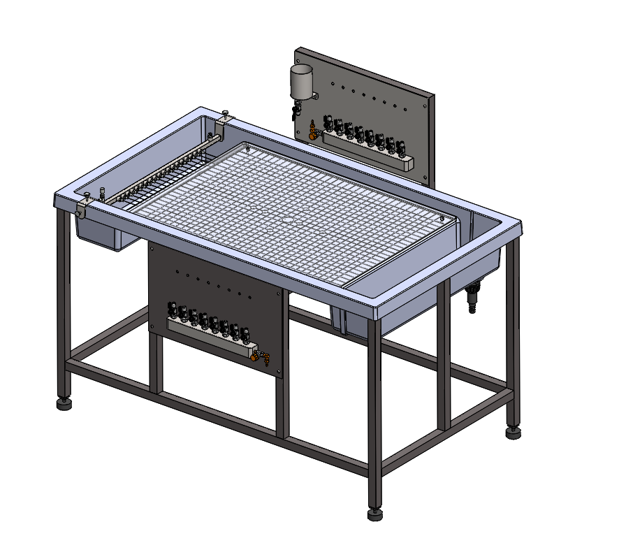
- LxWxH: 1200x800x950mm
- Weight: approx. 135kg
Description
Technical Specification
Media
The axial turbine operates as a reaction turbine as used in gas turbines and steam turbines. The water flows through a stator where it is deflected and accelerated. Then, the water hits then the blades where it delivers kinetic energy and pressure energy and puts the rotor in motion. The water pressure steadily decreases from the inlet to the outlet.
The trainer provides the basic experiments to get to know the operating behaviour and the most important characteristic variables of axial turbines.
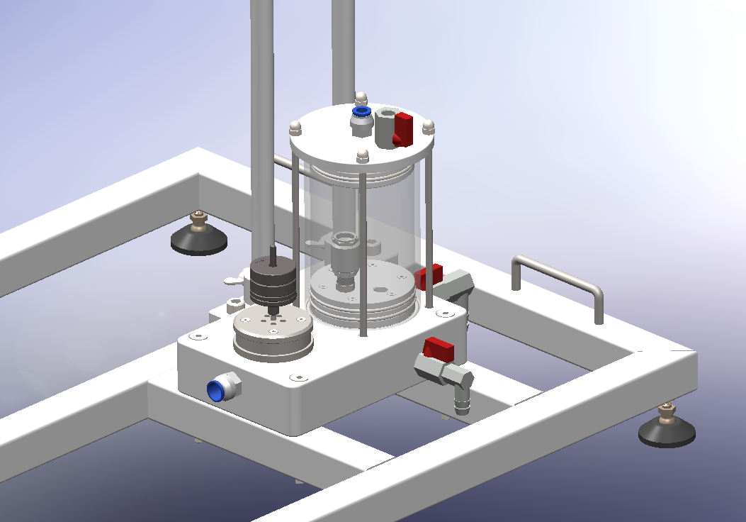
HM 287 features a closed water circuit with an axial turbine, a centrifugal pump and a water tank. The stator and the rotor of the turbine are mounted in a transparent housing and can be observed during operation. The loading device is outside of the housing. The eddy current brake generates a defined load. The eddy current brake is specially developed. It is wear-free and can be finely adjusted. The flow rate is adjusted using a valve.
The trainer is fitted with a sensor for pressure (turbine inlet). The torque produced by the turbine is determined via an electronic force sensor. The speed is measured with an optical speed sensor. The flow rate is determined by an orifice plate with differential pressure measurement. The microprocessor-based measuring technique is well protected in the housing. The measured values are transmitted directly to a PC via USB where they can be analysed using the software included.
All the advantages of software-supported experiments with operation and evaluation are offered by software and the microprocessor.
Learning Objectives
- Principle of operation of an axial turbine
- Determination of the power output
- Determination of the efficiency
- Recording of the characteristic curve
- Comparison of experiment and calculation
Axial turbine
- power output: approx. 130W at 3500min-1
- rotor, outer diameter: 50mm
- blade length: 5mm
Pump
- power consumption: 1,02kW
- flow rate: approx. 375L/min
- head: 13,7m
Measuring orifice
- diameter: 44mm
- differential pressure sensor: 0…0,1bar
Measuring ranges
- flow rate: 500L/min
- pressure (inlet): 0…5bar
- torque: 0…2Nm
Any questions? We are happy to help...
+49 40 670 854 - 0
sales@gunt.de
Newsletter
About Us
EduTech Lahore excels in designing and supplying cutting-edge equipment for Engineering Education in Mechanical, Polymer Chemical, Civil and Control Engineering. Focused on meeting the demand for quality education, we offer cost-effective solutions for the latest teaching equipment.
Contact Info
Head Office (Asia)
EduTech
Lahore
Regional Partner Office (UK)
Sales Partner (Middle East) GCC International FZC
Leave a Message
WhatsApp us