
State-of-the-art Engineering Equipment
FM-200| Laminar Flow Analysis Table
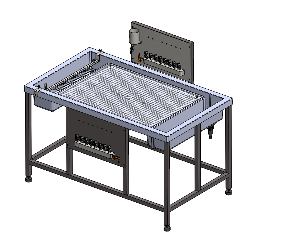
- Floor-standing apparatus demonstrates ideal flow
- Working section dimensions: 610mm x 892mm
- Actual viewing area: 495mm x 755mm
- A system of pipes, valves, and manifolds enables any configuration of sinks and sources to be used
- Includes dye injection system and adjustable knife-edge weir for rapid, accurate adjustment of table flow
- Required water supply for operation: 0.25 l/s at 2 bar
- LxWxH: 1300x800x1150mm
Description
Technical Specification
Media
Laminar Flow Analysis Table consists of two closely spaced sheets of laminated glass, arranged horizontally on a glass fibre moulding. An inlet tank and discharge tank are incorporated in the moulding, which is supported on a floor-standing, metal frame. Three adjustable feet enable rapid leveling of the flow table.
Eight miniature tappings, which may be used as sinks or sources, are arranged about the centre line of the lower glass plate in a cruciform configuration. A doublet (a sink and source in close proximity) is located at the centre of the pattern. A system of pipes, valves and manifolds enables any combination of the sinks and sources to be used. A row of control valves mounted above the flow table is used to adjust the flow through each individual source. A row of sink control valves is used to adjust the flow through each individual sink. A row of hypodermic needles attached to a manifold is positioned between the glass plates at the inlet edge.
The top glass plate may be raised at the front edge and retained in this position to enable models to be placed in the working section. A set of models are supplied for basic flow studies. These models are manufactured from plastic sheet and are trapped in the required position when the top glass plate is lowered. Alternative models can be fabricated from any convenient material and used to investigate the associated flow patterns.
Two-dimensional laminar flow is created between the two glass plates by the combination of low fluid velocity and the narrow gap between the plates. The resulting flow is free from turbulence and gives a close approximation to the behaviour of an ideal fluid.
Standards
- Machinery Directive 2006/42/EC,
Working Section
- Width inside moulding: 610mm
- Length of glass plates: 892mm
- Distance between glass plates: 3.2mm Approx
- Sinks/sources: 8 tappings in 7 positions
Models supplied
- 2 x canal banks
- 2 x rectangles
- 3 x cylinders
- 1 x aerofoil
Any questions? We are happy to help...
+49 40 670 854 - 0
sales@gunt.de
Newsletter
About Us
EduTech Lahore excels in designing and supplying cutting-edge equipment for Engineering Education in Mechanical, Polymer Chemical, Civil and Control Engineering. Focused on meeting the demand for quality education, we offer cost-effective solutions for the latest teaching equipment.
Contact Info
Head Office (Asia)
EduTech
Lahore
Regional Partner Office (UK)
Sales Partner (Middle East) GCC International FZC
Leave a Message
WhatsApp us