
State-of-the-art Engineering Equipment
EM-211.01 | Determination of Gear Efficiency
- LxWxH: 1060x600x420mm (experimental unit)
- Weight: approx. 35kg
Description
Technical Specification
Media
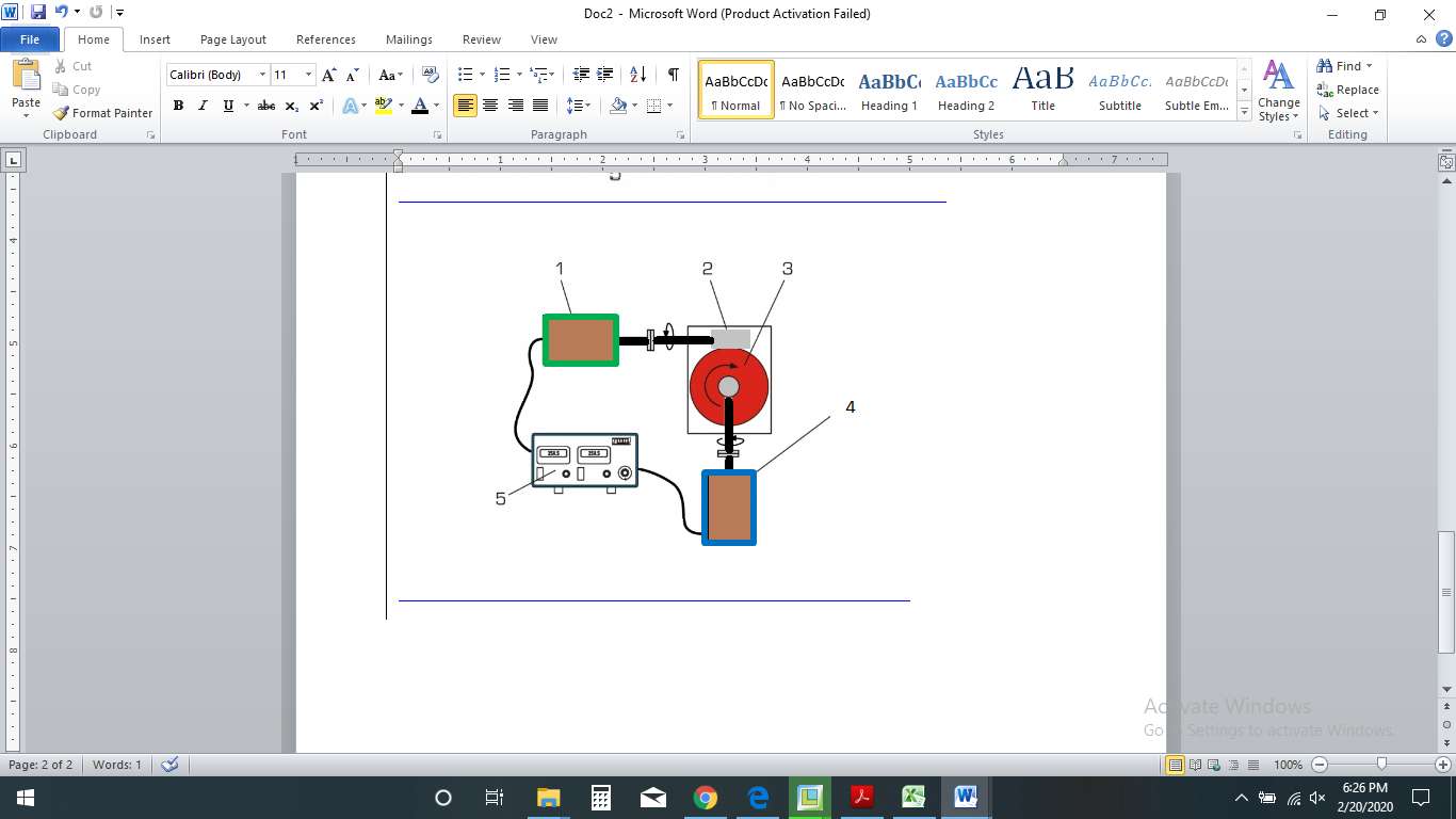
A complete test system with drive and brake unit and two different gears. Driving and braking power are calculated to determine the efficiencies.
The components used are common in drive technology and therefore closely related to practice.
A three-phase AC motor with variable speed via frequency converter serves as the drive unit. An electromagnetic brake is used as the brake unit. The constant braking effect can be very finely adjusted via the exciting current, it then serves as a tunable load.
The properties of the magnetic particle brake can be investigated in an additional experiment.
Experimental Capabilities
- Determination of the mechanical efficiency of gears by comparing the mechanical driving and braking power for a) Spur gears b) Worm gears c) Helical gears.
- Determine the speed ratios over gears teeth ratios.
- Determine the torque variations over the applied loading conditions.
- Determine of the backlash over
- Spur gears
- Helical gears
- Worm gears.
- Predictions of transmission ratios.
- Predictions of torque transmissions.
- Three -phase AC motor with variable speed of, power output: 0.20kW, speed: 0-2500 revolutions min – 1.
- Magnetic particle brake, rated braking torque at exciting current 0-0.2A: 0-8 Nm.
- Two-stage spur gear, transmission ratio should be minimum of 13.5 torque: min, 23.4Nm.
- Worm gear with minimum of transmission ratio: 15, torque: 10Nm, worm: z=2, worm gear: z=40.
- Measuring ranges:
- speed: 0-3000 RPM,
- force: 0-100N.
- Unit is compatible with the following single phase 230V, 50Hz, 1 phase
- LxWxH: 420x450x180mm (display and control unit)
Any questions? We are happy to help...
+49 40 670 854 - 0
sales@gunt.de
Newsletter
About Us
EduTech Lahore excels in designing and supplying cutting-edge equipment for Engineering Education in Mechanical, Polymer Chemical, Civil and Control Engineering. Focused on meeting the demand for quality education, we offer cost-effective solutions for the latest teaching equipment.
Contact Info
Head Office (Asia)
EduTech
Lahore
Regional Partner Office (UK)
Sales Partner (Middle East) GCC International FZC
Leave a Message
WhatsApp us