SM-213 | Two Hinge Parabolic Arch

- Visual reality of an Arch
- Seven load points. Loads can be applied at the same time, not one at a time
- Horizontal thrust measured via load cell
- Weights set supplied as standard
- LxWxH: 1060x100x500 mm
- Weight: approx. 35 kg
Description
Technical Specification
Media
The steel Parabolic Arch with uniform cross section has a span of 1.0 meter and a rise of 0.2 meter. One end is pinned in precision bearings set in a fixed springing attached to the Universal Frame and Stand. The other end has bearings running on a track plate to which is attached an integral load cell for measuring the horizontal thrust created when the arch is loaded. The horizontal thrust is created by applying loads on the arch via seven equi-spaced load and hangers vertically suspended from the arch.
For model analysis measurements, pins are set on the arch at each Load hanger. A dial gauge on a moveable stand is also provided for this work. The load cell and dial gauge output must be fed into the Interface.
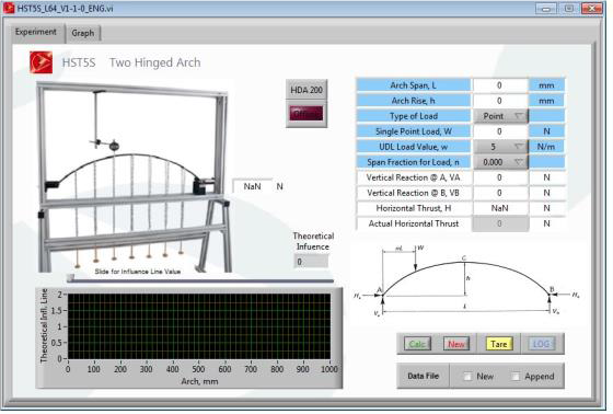
 Microcontroller based electronics system fully instrumented and computer controlled via USB / Ethernet interface /WiFi to record / set process parameters and to perform related force calculations. (Computer not include).
The experiments are carried out more effectively. The final result reliability is much higher without doubt, therefore the work done by the researcher possess a higher credibility.
Software
 Microcontroller based electronics system fully instrumented and computer controlled via USB / Ethernet interface /WiFi to record / set process parameters and to perform related force calculations. (Computer not include).
The experiments are carried out more effectively. The final result reliability is much higher without doubt, therefore the work done by the researcher possess a higher credibility.
Data Storage
The data are stored in a data base either in file format supported by third party software. The data can be represented both numeric format or graphic format like their trends and distributions independently the way it is used. As being available for the users anytime allows different tests to be compared and reach conclusion more truthful.Learning Objectives
- To examines relationship between applied loads and horizontal thrust
- To compare the horizontal thrust at springing with simplified theory
- Uses influence line for horizontal thrust
- Derivation of influence line for horizontal thrust
- 1x Steel arch of uniform cross section 40 x 8mm
- Span of 1.0 meter and rise of 0.2 meter
- Vertical loading from seven equi-spaced points across the arch (125mm intervals)
- 7x Hanger
- 7x chain
- 1x Digital Dial Gauge with cable
- 7mm travel; 0.01mm resolution
- 1x Load Cell
- 0…500N
- 1x Load cell track plate
- 1x Flat anvil
- 1x Tape measure
- 1x Accessories container
- 1x Hex wrench
- 1x Instruction manual
- 1x e-book
- 1x Complete Software
- 1x Packing list
- 1x Test sheet
- Weights set: 1 x 0.1N, 2 x 0.2N, 1 x 1N, 2 x 2N
- Weights set: 10 x 5N, 8 x 10N, 3 x 20N, 1 x 50N
Any questions? We are happy to help...
+49 40 670 854 - 0
sales@gunt.de
Newsletter
About Us
EduTech Lahore excels in designing and supplying cutting-edge equipment for Engineering Education in Mechanical, Polymer Chemical, Civil and Control Engineering. Focused on meeting the demand for quality education, we offer cost-effective solutions for the latest teaching equipment.
Contact Info
Head Office (Asia)
EduTech
Lahore
Regional Partner Office (UK)
Sales Partner (Middle East) GCC International FZC
Leave a Message
WhatsApp us
